Code SchematicLast Update: Jan. 30, 2003
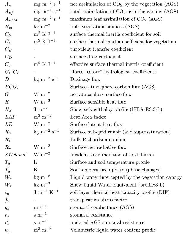
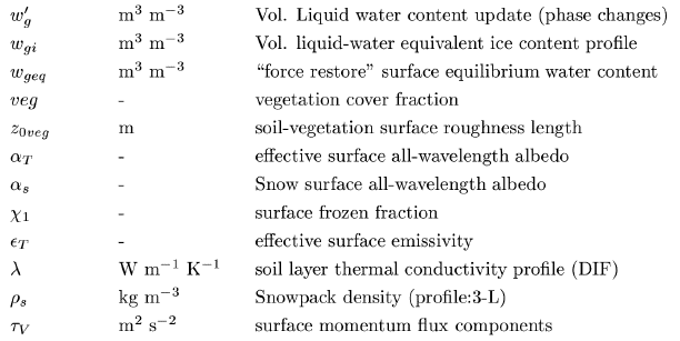
The first (leftmost) column represents the DRIVER of ISBA This program reads input forcing and parameters, outputs diagnostics, and performs budget computations. The dashed line represents time integration of ISBA: there are several nested do loops (year, days, forcing time step, model time step...). ISBA is called within the inner-most loop. The second (middle column) has the "first-layer" routines, i.e. those called directly by ISBA, each representing a specific physics module. Options are indicated using the symbol (as shown) with the character string for each option listed. The "main" output or in/out variables are indicated. The symbols are defined in the symbols_e.ps file: the symbols are consistent with ISBA-related publications for the most part. The last (rightmost) column contains the "second-layer" routines: those routines which are either i) shared between different ISBA modules (such as the aerodynamic resistance computation or the tridiagonal matrix solver), or ii) which are simply further subdivisions of the main module (eg. the 5 HYDRO routines). Some routines are color-coded corresponding to options: green for Ags (CO2 module), blue for the soil-diffusion option, and pink for the 3-layer explicit-snow scheme option. Symbols:

|